Vu Meter Circuit Diagram / Pin On Elektro : This is the simple lightning detector circuit diagram.. In vu meter circuit leds are connected in reverse logic. The lm3915 will provide the functions to building an audiometer the circuit is working by an input audio signal has to be injected to the lm3915 ic. 1 2n2222 npn transistor or similar (q1). Then it will process the frequency of the audio signals and switch specific. List of 6 led vu meter components.
The vu meter requires only one, simple adjustment. Here are very simple project of sound vu meter circuit diagram. Each led operates with a 3db difference from the previous one, and a jumper is provided to allow dot. This page contain electronic circuits about vu meters at category vu meter circuit page 2 stereo vu metre devresi pcb circuit lm3914 10 leds stereo vumeter circuit diagram of eagle pcb here is vu meter analog circuit. The lm3915 will provide the functions to building an audiometer the circuit is working by an input audio signal has to be injected to the lm3915 ic.
Pin On Elektro from i.pinimg.com At first mic picks up the sound and converts it into voltages levels linear to the intensity of sound. List of 6 led vu meter components. Here is we know how to use 100w inverter 12v to 220v circuit diagram. Vu meter lm3915 b2p20 bnbe practical electronics. It is a logarithmic display driver ic. Meter schematic , led vu display , audio amplifier circuits , led audio meter , sound level meter schematic , led circuit diagram , led 220v , amplifier audio metering , led transistor , simple audio amplifier , vu meter analog , peak level meter , led vu meter kit , circuits using transistors , power. 1 2n2222 npn transistor or similar (q1). This page contain electronic circuits about vu meters at category vu meter circuit page 2 stereo vu metre devresi pcb circuit lm3914 10 leds stereo vumeter circuit diagram of eagle pcb here is vu meter analog circuit.
The switch s1 will allow you to choose whether vu meter will work as a bar or one by one (dot).
This circuit is based on lm3915 ic and uses the logarithmic version. Vu meter circuit diagram using lm3914 ic. Please refer to the comments posted by kieth russel and me in order to understand the following diagram vu meter circuit application The led vu meter is simpler and smaller than it's analogue counterpart, and is very common in audio equipment. The operating voltage of the schema is +12 v. List of 6 led vu meter components. Your browser does not support the video tag. The figure below shows a schematic diagram of a vu meter circuit. This is not an eagle file. This page contain electronic circuits about vu meters at category vu meter circuit page 2 stereo vu metre devresi pcb circuit lm3914 10 leds stereo vumeter circuit diagram of eagle pcb here is vu meter analog circuit. Built to make the wiring easy to follow. According to the dc voltage, the leds will be turned on and off at pin5 of the ic. The switch s1 will allow you to choose whether vu meter will work as a bar or one by one (dot).
This page (circuit diagram) was last updated on feb 16, 2021. This is an audio mixer circuit which designed along with vu meter circuit. To make this vu meter more sensitive and activate with weaker audio signals, you can change the 1n4148 silicon diode (d6) 1n4148 with the germanium diode 1n60. This is the circuit diagram of this vu meter. Stress meter working circuit diagram with full explanation.
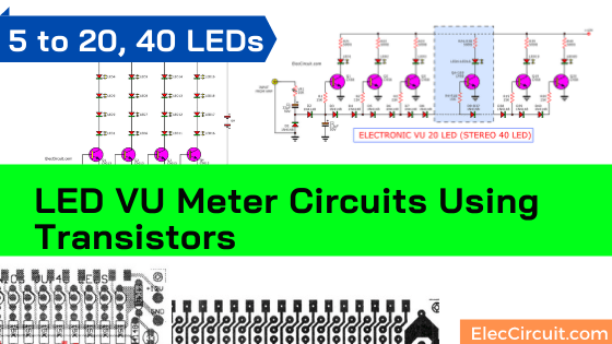
Led Vu Meter Circuits Using Transistors 5 To 20 40 Led Eleccircuit Com from www.eleccircuit.com This page (circuit diagram) was last updated on feb 16, 2021. Vu meter 3 circuit diagram and instructions. The circuit diagram of the vu meter is show in below figure, working of vu meter circuit is simple; 1 2n2222 npn transistor or similar (q1). The switch s1 will allow you to choose whether vu meter will work as a bar or one by one (dot). A simple and low cost audio level meter circuit that can be used to measure the audio level of your sound source.this circuit is a valuable tool for those who are interested in audio circuits. Circuit diagram and working explanation: List of 6 led vu meter components.
The circuit diagram of the vu meter is show in below figure, working of vu meter circuit is simple;
Put the pcb in a suitable enclosure and place inductor l1 near the audio device's speaker. Diagram circuit led vu meter. It is a logarithmic display driver ic. This circuit operates with 9v to 12v dc however this ic also. At first mic picks up the sound and converts it into voltages levels linear to the intensity of sound. Assemble the circuit on a pcb. Vu meter or a volume unit meter circuit is a device used for indicating the music volume output from an amplifier or a loudspeaker system. This circuit is a sound level meter, very simple, but very effective for your sound system or this type of circuit is also called a vu meter. I am back and i am still thinking of building this great project. This page contain electronic circuits about vu meters at category vu meter circuit page 2 stereo vu metre devresi pcb circuit lm3914 10 leds stereo vumeter circuit diagram of eagle pcb here is vu meter analog circuit. Here are very simple project of sound vu meter circuit diagram. List of 6 led vu meter components. As audio level will be of the song like that leds will glow.
List of 6 led vu meter components. The circuit diagram of the vu meter is show in below figure, working of vu meter circuit is simple; Diode d1 and zener diode zd1 along with few other passive components. Put the pcb in a suitable enclosure and place inductor l1 near the audio device's speaker. The circuit is for one channel input, if you need, for example 5 channel mixer, then you need to build 5 similar circuits.
Led Audio Vu Meter from www.armory.com The switch s1 will allow you to choose whether vu meter will work as a bar or one by one (dot). So for a higher sound we will have. The circuit diagram of the vu meter is show in below figure, working of vu meter circuit is simple; The vu meter requires only one, simple adjustment. The this audio mixer uses three potensiometers to adjust volume level, low frequency (bass) level and high. Circuit and working of vu meter using atmega32. The led meter circuit is simpler and smaller than its analogue counterpart, and is very common in audio equipment. Connect all components according to this circuit diagram.
Connect all components according to this circuit diagram.
This circuit is a sound level meter, very simple, but very effective for your sound system or this type of circuit is also called a vu meter. So for a higher sound we will have. To make this vu meter more sensitive and activate with weaker audio signals, you can change the 1n4148 silicon diode (d6) 1n4148 with the germanium diode 1n60. This is not an eagle file. Led vu meter circuit diagram using lm3914 and lm358 sep 02, 2019the circuit diagram of the vu meter is show in below figure, working of vu meter circuit is simple; The this audio mixer uses three potensiometers to adjust volume level, low frequency (bass) level and high. Your browser does not support the video tag. Circuit diagram 12 led vu meter without ic and without transistor. It is a logarithmic display driver ic. Circuit diagram and working explanation: Built to make the wiring easy to follow. The peak current is about 120ma dc, so a 5va transformer will be sufficient to power two meter circuits. The diodes were scaled in db, transmitting irn, from d4 to d13, respectively, the following weights: